


Centrifugal brakes
Safe speed limitation using centrifugal brakes
Powerful brakes ensure reliability – our centrifugal for your safety!
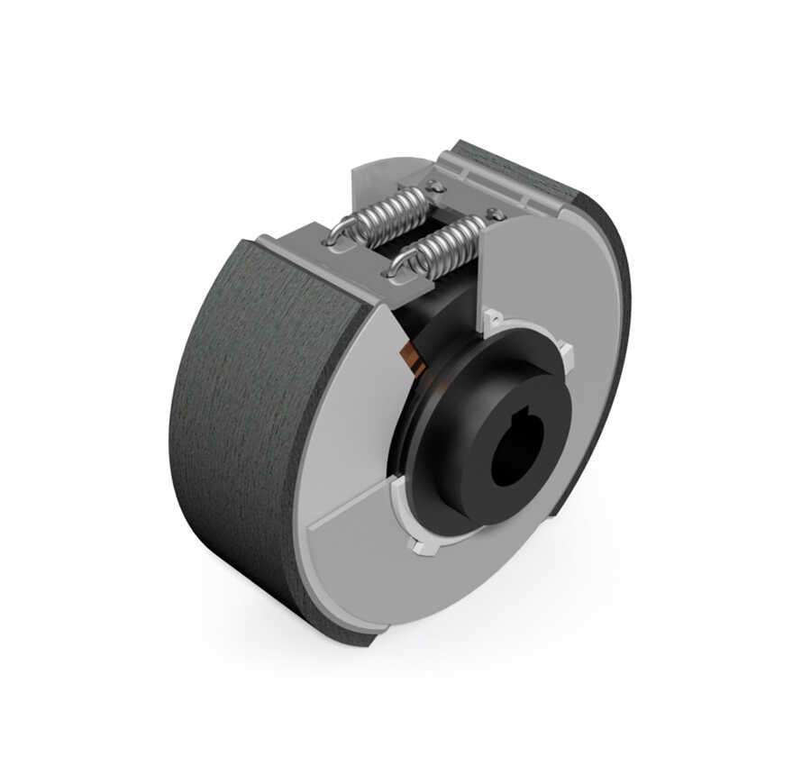
Every centrifugal brake offers this
Do you need a centrifugal brake to secure your users and applications? Then you have come to the right place. The centrifugal brake operates on the same principle as our centrifugal clutches – except that here the housing is fixed and secured against rotation, rather than rotating itself.
Benefits at a glance
Technical depth
Operating principle
Guided weight elements set in rotation experience a radial force component which accelerates them outward. This force is compensated by spring forces up to the defined engagement speed.
When the switch-on speed is reached, the friction linings are in contact with the housing and the torque build-up on the housing begins. Increasing the speed leads to quadratically increasing forces and thus to increasing torques. The brake is at the beginning of the operating range. The working range is between switch-on and the torque equilibrium between load torque and braking torque. This torque equilibrium must lie in the slip range of the brake.
As long as the centrifugal brake is not switched on, so the spring force outweighs the centrifugal force, the system operates without contact and without losses. In order not to affect the brake function, fat, oil and wetness must be kept away from the friction surfaces.
By varying the springs, the friction material, the size, the number of parallel elements and the operating speed, the engagement speed and torque are determined and adapted to the specific application.
Switching on
Fundamentally, the switch-on speed depends on the balance between load torque and braking torque. Since the power of a centrifugal brake increases with the square of the speed, a minimum operating speed of the braking system is required.
The engagement speed of a centrifugal brake describes the rotational speed at which the mass of the centrifugal weights, due to the centrifugal forces acting upon them, overcomes the retaining force of the springs. By choosing springs of varying strengths, which hold back the centrifugal weights for different lengths of time, the engagement speed can be varied. Due to these relationships, a centrifugal brake cannot decelerate a system to a complete standstill; they frequently serve as speed limiters.
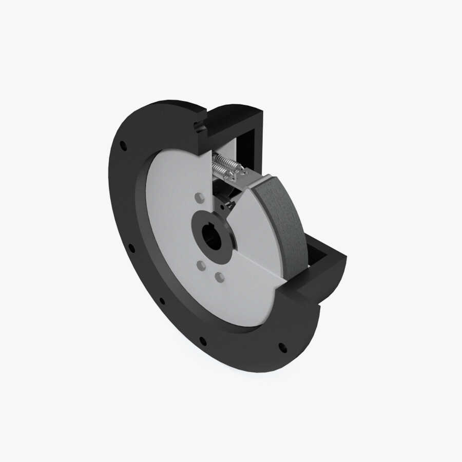
Dimensioning
Centrifugal brakes are generally safety-critical components – careful design is therefore essential. The following parameters are crucial:
• Operating speed
• Switch-on speed
• Frequency of braking manoeuvres
• Braking duration
Heating
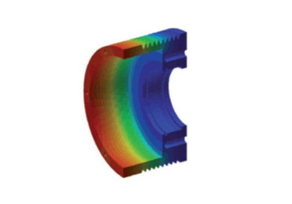
Friction generates heat, so a centrifugal brake converts the friction work done completely into heat. The heat is generated directly in the frictional contact and essentially heats the material directly involved in the frictional contact (see fig.).
The heat generation is dependent on the respective operating conditions as well as the following factors:
- Braking torque
- Size of the clean area
- Braking time
Through thermal conduction, a heat distribution is established throughout the entire brake. The temperature rises sharply at the beginning of braking and flattens out as it continues until a maximum is reached. When designing a brake, care must be taken to ensure that the maximum permissible temperatures at the frictional contact are not exceeded, otherwise significantly increased wear will occur on the friction lining.
This thermal overload causes the coefficients of friction to change significantly and may adversely affect the brake’s performance. Due to the surface temperatures generated, protective devices may be required in the vicinity of the brake.
Structure
Each centrifugal brake consists of a profiled hub on which centrifugal weights are held together by lining hanger with brake linings (friction material) by tension springs. The inner workings of the brake are pressed into the brake housing with bearings and secured by cover discs and circlips.
Areas of use
The main application area lies in speed limitation during the safe lowering of people or loads – from descenders to leisure applications such as zip lines.

An overview of our
centrifugal brake with intermediate housing for rack-and-pinion drive
Centrifugal brake for installation in customer-supplied housing
Centrifugal brake for flange mounting with a closed housing
centrifugal brake with intermediate housing
Do you have any questions? Please contact us.
Product enquiry form
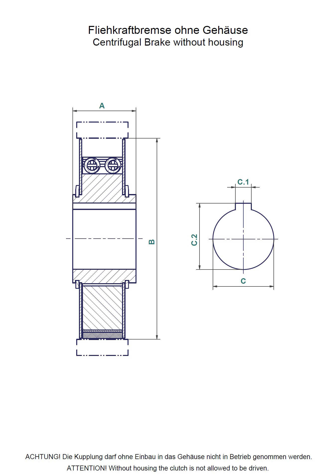
Centrifugal brake without housing
If you are looking for a specific drive concept, we recommend our product request form in which you can comfortably enter the necessary details.
Or you can print out the drawing, enter your dimensions and upload the scanned document to the form under "Upload", which you send to us.
© copyright 2026 | Amsbeck
Boschweg 15
D-48351 Everswinkel
Germany